Fall 2022 ︎︎︎ SUNY Purchase ︎︎︎ (DES3090) Interactive & Experience Design
Knitting circle: digital in & Out
Introduction
In our Warm-ups we’ve been “locked into” the buttons and neopixels on the CPX itself. This is great as we don’t need to know anything about electronics to get up and running. However, as you develop ideas you may want to work with buttons, lights, devices and sensors external to the CPX. Here we’ll look at how to do just that. Materials
For this we’ll use this arcade button with a light inside it, and several alligator clips. If you want these specific ones, you can find them on Adafruit (linked below)30mm Arcade Button with LED (white)︎
 Alligator Clip Test Leads (13 inches, 10 pack)︎
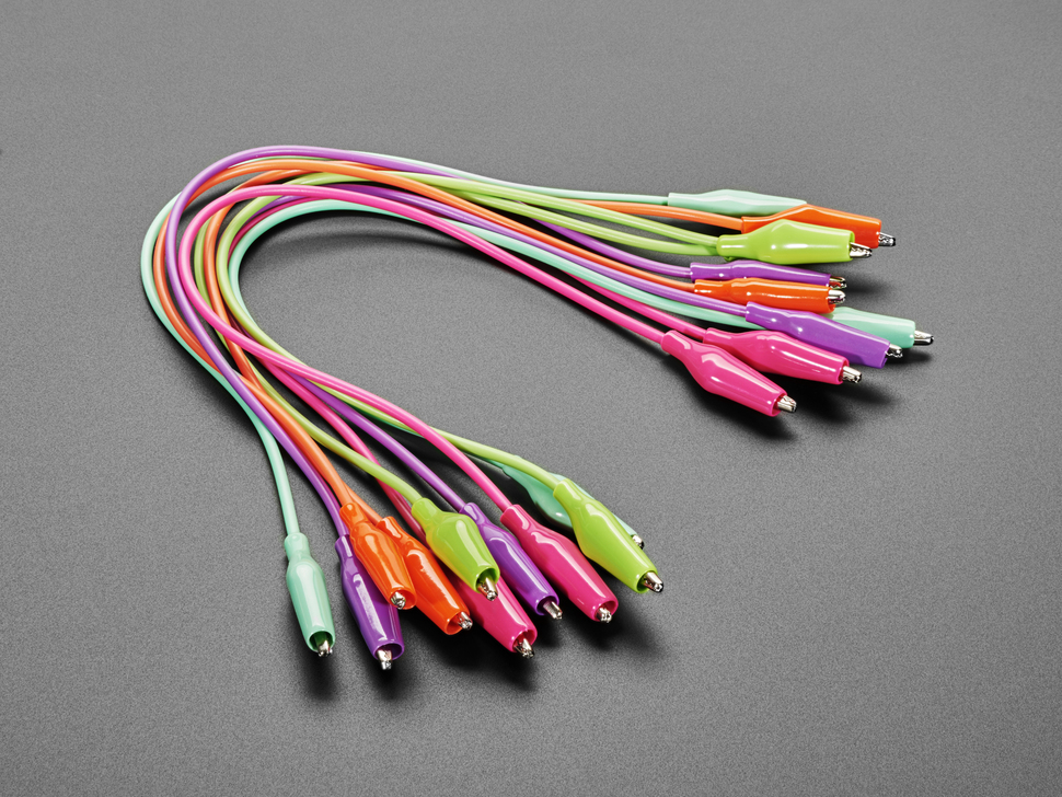
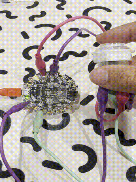
Ultimately, we want to do this:

The ole in & out
What we need to understand to do this is digital input and output. Digital in this case means that the value of the input or output is only 1 or 0, on or off, true or false. Input means a signal that goes into the CPX, like a button (pressed or not pressed), whereas an output is something that gets sent out of the CPX like a light or the neopixels. We say this in opposition to analog in this context. Analog input would be something like a rotating knob (or potentiometer), used to set volume or brightness. Analog output could still be a light that becomes dimmer or brighter. We’ll refer to the rings on the outside of the CPX colloquially as “pins.” This is common parlance in electronics for the pins or legs on an integrated circuit. These usually have discrete and defined functions.
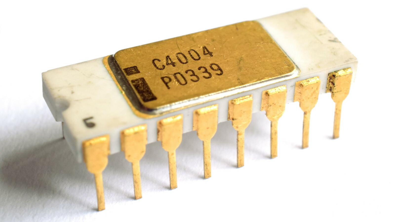
The 4004 (Photo: Thomas Nguyen, CC BY-SA 4.0, via Wikimedia Commons)
On the CPX, some of the pins are labelled with an A and then a number. These are the ones we will be working with. The unique functionality they provide is that they can be either input or output, we must say that we want to do this in code.
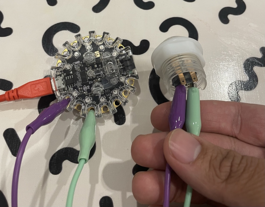
To use our button as an input, we need to connect it up first. Find the two prongs that are emanating from the plastic inside the button (the bottom-most ones in the image below).
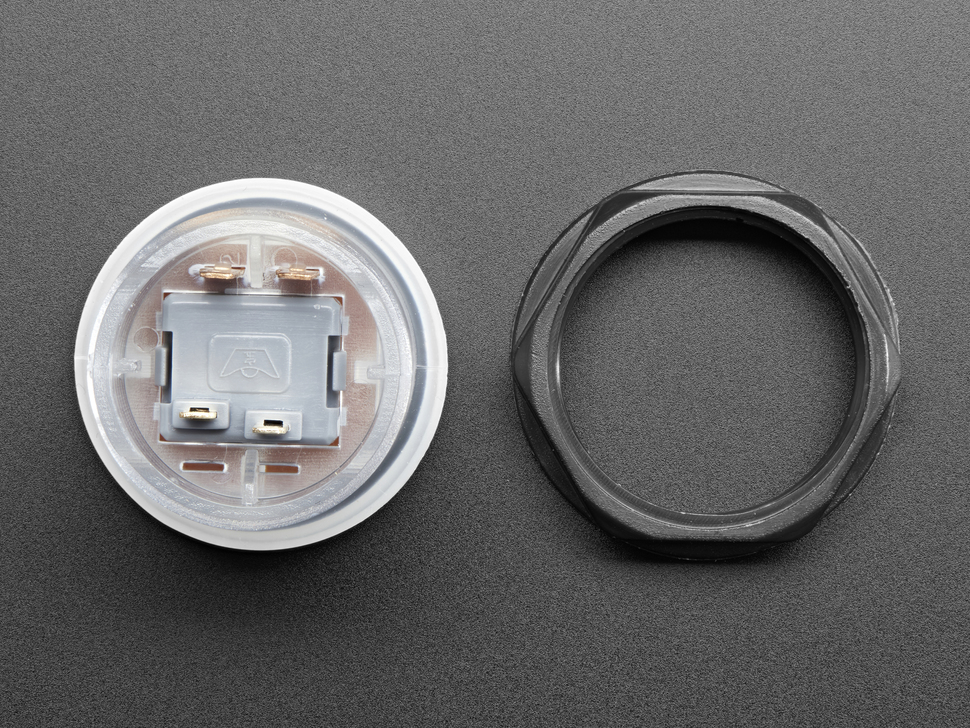 The bottom two pins in this image are the ones that connect to the button, the others connect to the light.
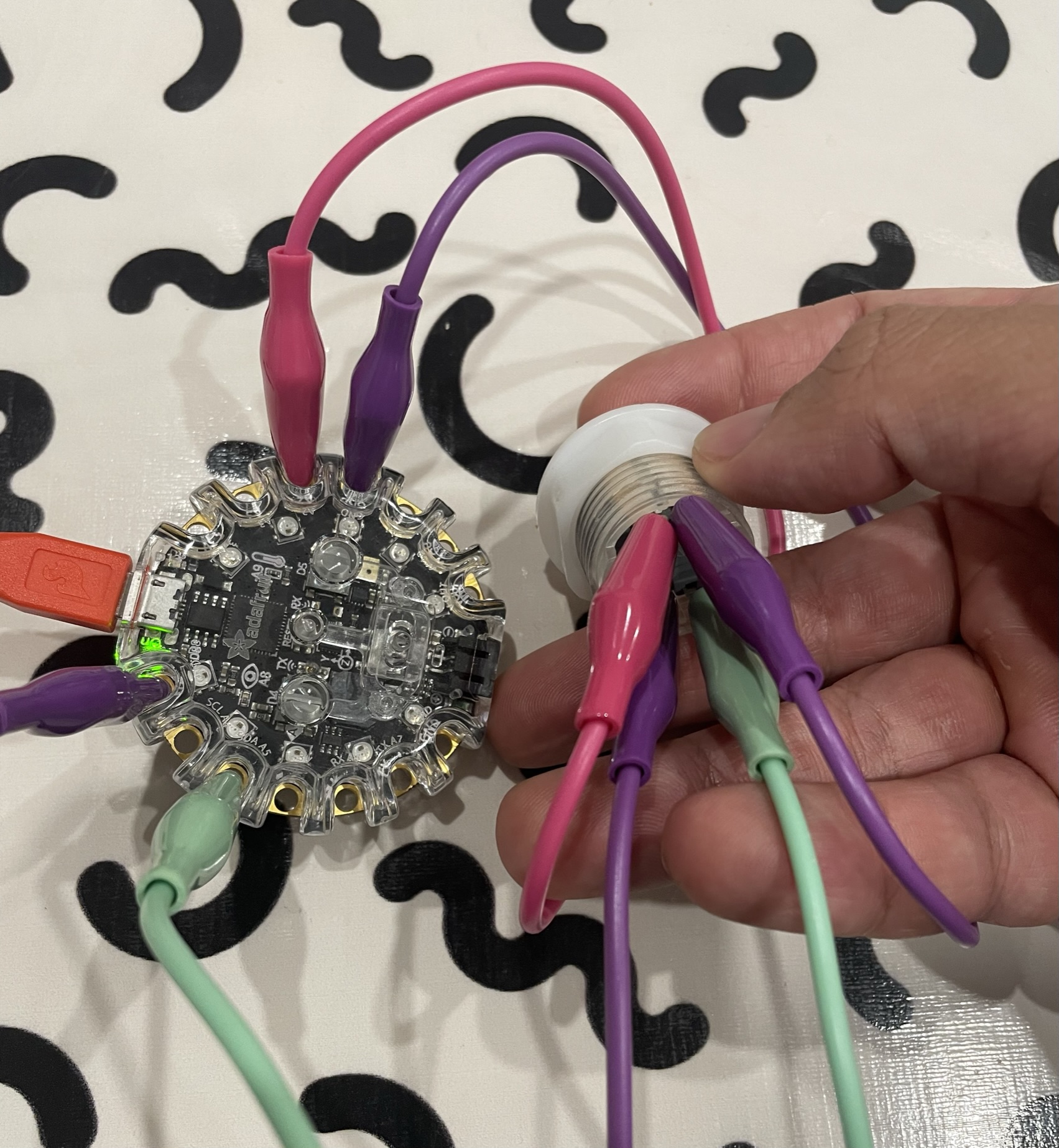
 These connect to the button, the others connect to the internal light. Use alligator clips to connect one to the pin labelled A5 on our CPX and one to any pin labelled “GND” (there are several). This stands for ground. This means that we are completing the circuit that not pressing the button interrupts. This idea may be a bit abstracted by not seeing where power is coming from, and the complexity of the circuit on the CPX. You don’t need to totally understand the electronics behind this but need to know that for a digital input like this, one pin should be connected to the pin we are reading, and one pin will be connected to ground. It should look like the below image.
Note that typically a black cable is connected to ground for visual clarity. In our case I used the closest color I had which was purple. There’s nothing special about a black cable, this is simply a courtesy or tradition, not a binding rule.
In order to read this specific pin as an input, we need code that looks slightly different than we’ve seen before. Here’s what we need to do︎︎︎
Now if we want to use the button internal to the arcade button, we have to hook it up like so:
We add a little bit of code. We simply have to set our desired pin as output and then set the “value” to true when we want it to light up. It looks like this︎︎︎
That’s it! I have other buttons and lights you can try and if you see anything on adafruit or sparkfun that you’d like to try out and can’t quite figure out feel free to bring it to class and talk about it!
︎Back to Interactive & Experience Design