LED Fade
Okay, so we initially made our LED simply turn on and off. In order to do that, we need to understand a concept called PWM which stands for Pulse Width Modulation.
Pulse Width Modulation
Pulse Width Modulation simply means that we turn the LED on and then off very quickly, and are very careful about how long the LED is on versus off. By making the amount of time the LED is on shorter than the time it is off, we start to make it appear as if the LED is dimming and vice versa if we increase the amount of time the LED is on.The amount of time the signal is on versus off is known as the duty cycle, and is expressed as a percentage. So the time the signal is on or doing it’s duty so to speak is lower for dimmer and higher for brighter.
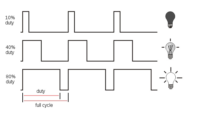 A visual representation of the duty cycle
You might have experienced this phenomenon if you’ve ever played with a synthesizer that has this feature, by name.
In theory, we could just use the command we already know, digitalWrite() to achieve this effect. However, if you play with the code to the left, you’ll see that it quickly becomes cumbersome to manage and work with before the effect starts to...fade (sorry︎).That is to say, we see the LED starting to flicker rather than smoothly fade.
In truth, we functionally need to know very little about the science behind this concept, we just need to know one new function, called analogWrite().
In truth, we functionally need to know very little about the science behind this concept, we just need to know one new function, called analogWrite().
Analog versus digital
On a more basic level, we need to understand the difference between digital signals; which can simply be on and off and analog signals that can be expressed in a range of values. AnalogWrite() is the same as digitalWrite() except that we can give ourpin a value between 0 and 255 rather than just HIGH or LOW.[image analog vs digital signal]
Here’s the code we upload to our board
We use a simple for loop (link to for loops) to make our LED fade on and off. Using the analogWrite() function, we just give it a number and the arduino does the rest behind the scenes with modulating the pulse width and managing the duty cycle and all that.
Here’s the circuit, it’s the same as before, except we use pin 9.
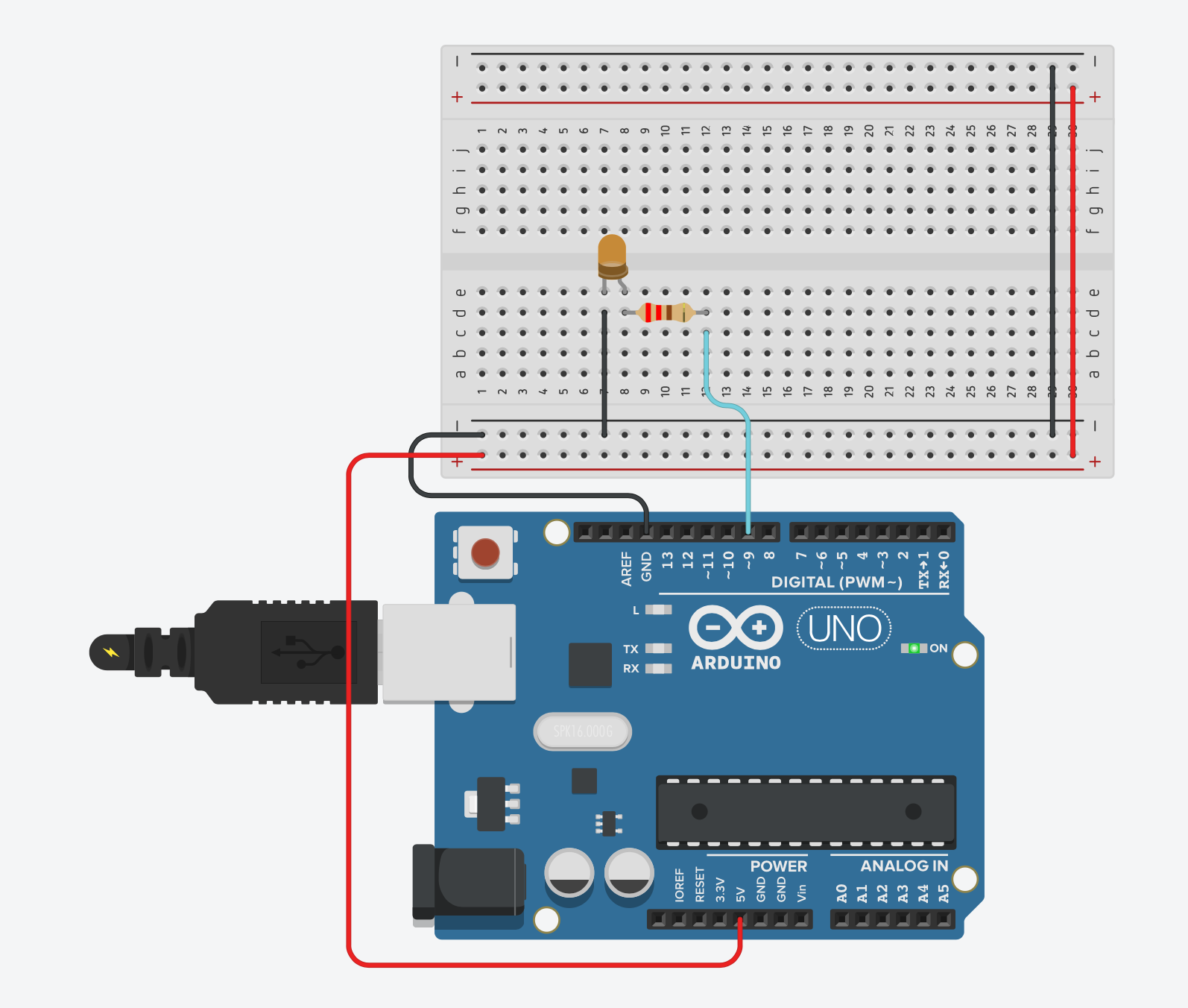
The reason for this is that pin 9 has PWM. We know this because, if we look at our arduweeny, we can see that some of the pins on the digital output side have a squiggle or tilde in front of the number.
 see pins 11, 10, 9, 6, 5 and 3 here
Here are some exercises
- Create a circuit for two LED’s, and make them fade into each other at different rhythms.
- Cycling fading.
- Find a red, blue and a green LED and create a circuit for them and place them close to each other. For added effect, place a sheet of thin paper or vellum folded in a box of sorts to diffuse the light. Having done that, make the colors fade between different values by combining the light. It won’t be perfect, but for example, red and blue together will become purple.