DES3090→
Interactive & Experience Design→In-class Team project
DES3090
→
Interactive & Experience Design
→
In-class Team project
In this class we’ll break into 3 “teams,” each team will produce part of a project that we’ll eventually combine together into one bigger project.
team 1
Make an arduino sketch that utilizes the joystick in order to change the color of an RGB LEDTEAM 2
Make an arduino sketch that utilizes an active buzzer in order to make a tuneteam 3
Make a processing sketch with two squares that change colors upon touchingTeam 1
→
Joystick + RGB LED
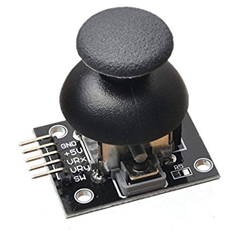
Joystick Module
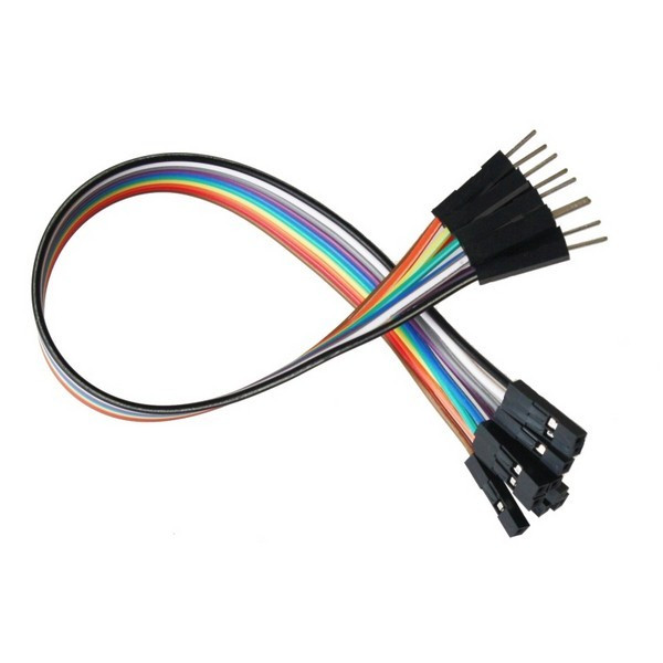
5 “male” to “female” jumper wires
yeah, wire terminology is gendered like this maybe worth considering for a project, n’ahm shayin?
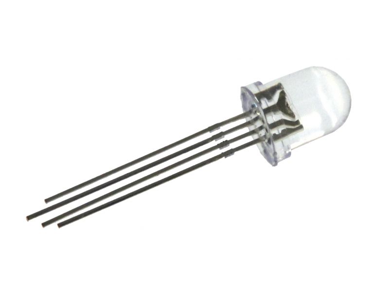
RGB LED
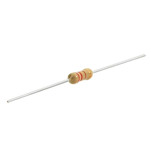
3 220 Ohm resistors
(red red brown)
(red red brown)
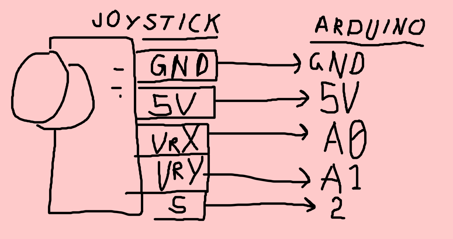
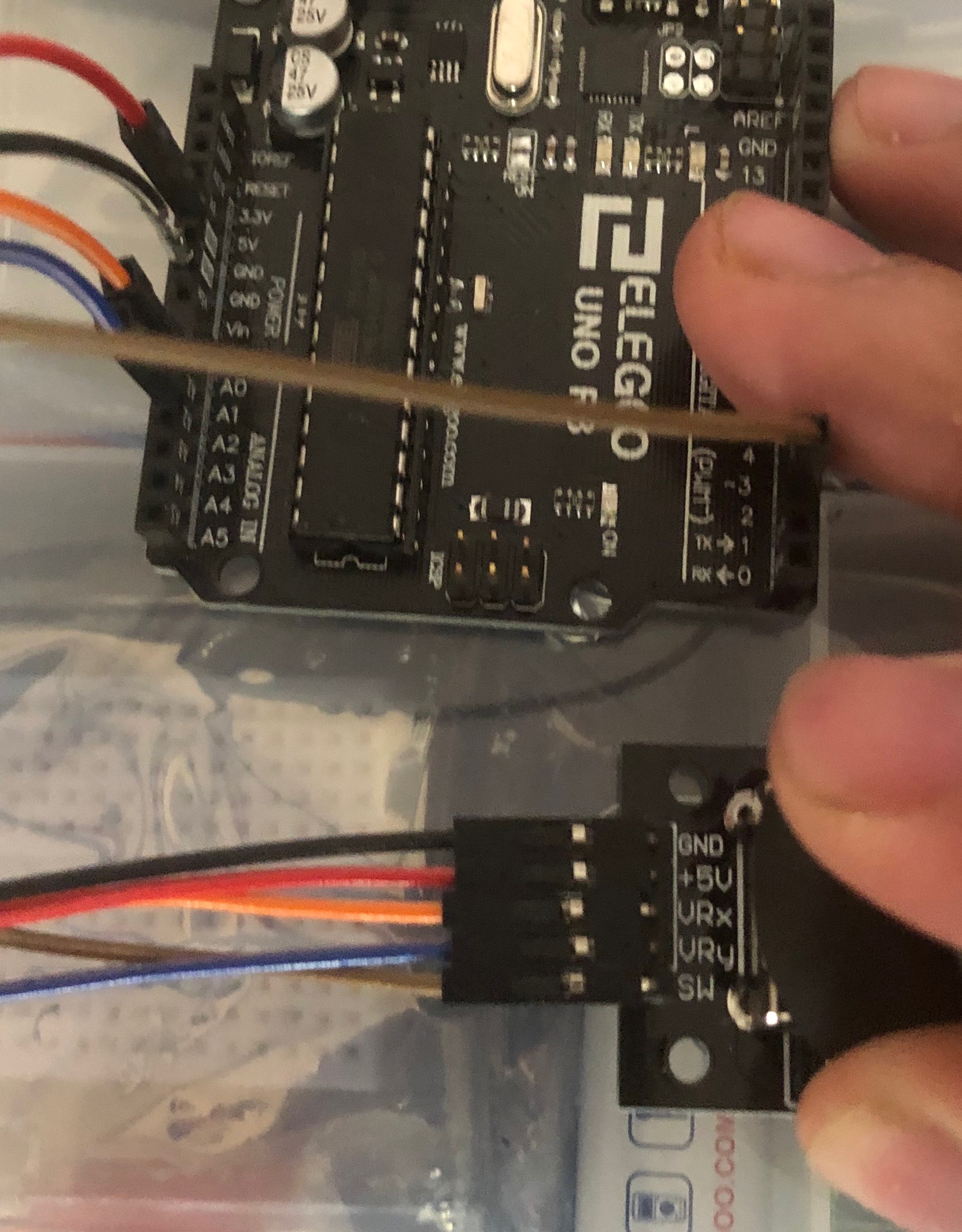
the Joystick module
Isbasically 2 potentiometers and a switch. One potentiometer controls the x-axis, one potentiometer controls the y-axis, the switch is activated when you press down on the joystick. So we have already seen all the code for this we just have to put it all together. Here, take a look:Here’s how you hook up the joystick (sorry tinkercad doesn’t have a joystick)
The RGB LED
So technically you have had access to this sketch which tells you how to hook up and work with the RGB LED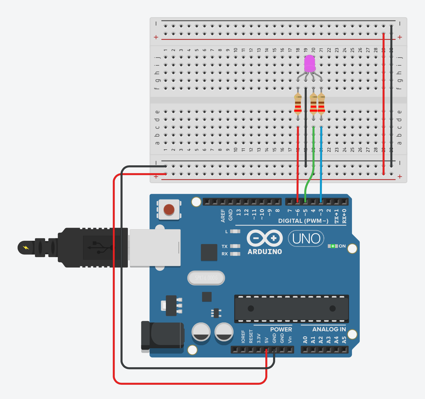
Lil math alert (absolute value)
In my example I made it such that, when the joystick is at rest or “neutral” then it will be “off” and at either extreme it will be either red or blue, and then form a version of purple as you twiddle the joystick.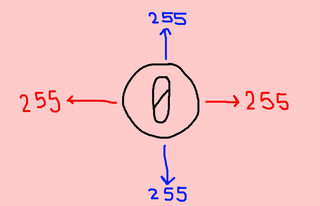
If you want to do this you’ll need to know a little useful mathematical thing called “absolute value” or the function abs(number). Whatever the number is will end up being positive, so abs(-255) will be 255.
If we use the map() function and set the range of the LED to be from -255 to 255, and then absolute value it, we will get 255 to 0 to 255.
Team 2
Team 2
→
Buzzer
For this project you’ll just need the active buzzer (and breadboard + wires)
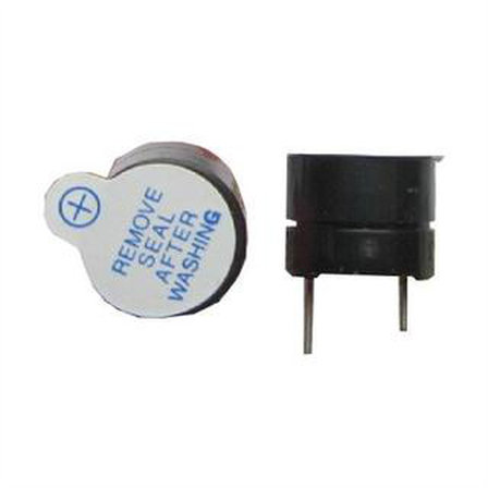
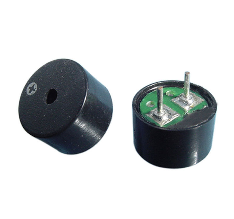

One way to identify the active buzzer is the sticker it usually comes with.
The other way to identify them is that the passive buzzer (above) has a little circuit board underneath.
Alternatively, the active buzzer has epoxy (black stuff) underneath.
the hookup
Hooking this up is very simple; attach the buzzer directly to the arduino. With pin 11 at the positive end (buzzers are polarized), and the negative to groundHow does this work?
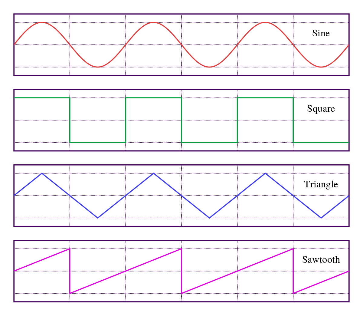
You’ll notice that pin 11 is a PWM pin. We used this previously to change the LED being on or off very quickly to create the impression that the LED is getting brighter or dimmer. If you’ve ever used a synthesizer, you’ll notice this is a square wave.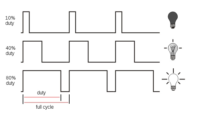
As an experiment try the “LED Fade” example, change the pin to 11 (where our buzzer is) and upload it to your board.
Luckily we don’t have to write a complex series of analogWrite()’s in order to get “musical” sounds out of our buzzer. The arduino folks gave us two little functions to do this easily tone() and noTone(); tone() simply needs two parameters, our pin and the frequency. noTone() gives us a “rest” of sorts, it simply produces no tone at the given pin.
MIDI is a protocol which stands for “Musical Instrument Digital Interface.” rather than producing sound; it produces the information about the musical sound we are producing from a digital device like a keyboard.
First select a piece of music; think of something with a clear melody, and then look for a MIDI file of it. I picked Bach’s Sinfonia to Cantata No. 29 because of this and also because it is the first song from the amazing album Switched-On Bach by seminal trans electronic musician Wendy Carlos (You may know her work from the soundtrack to A Clockwork Orange).
Opening the midi file in Garage Band will give us something like this
Unfortunately, our buzzer cannot reproduce all this information. However, you can try multiple buzzers if you find a good two part invention, or maybe an arrangement for a barbershop quartet song in MIDI form.
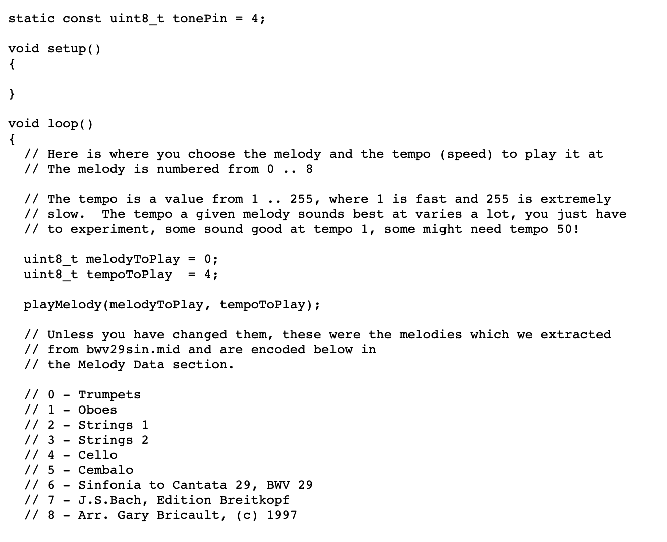
So now we need to convert our MIDI file to “tones()” that the arduino understands. Many people have already done this but I used this site.
You simply upload your MIDI file and then you’ll just need to adjust the code it gives you to use the proper pin, adjust the temp and select the correct “track” to play. Here’s what that part of my code output looked like.
You simply upload your MIDI file and then you’ll just need to adjust the code it gives you to use the proper pin, adjust the temp and select the correct “track” to play. Here’s what that part of my code output looked like.
TEAM 3 →PROCESSING
TEAM 3
→
PROCESSING
In theory, you have all the code you need to create this, you’ll just need if statements to check if the keyboard is being pressed and if the squares are overlapping, rectangles, and keyPressed(), keyReleased().
I think a good idea is to plan everything out on paper first very clearly and explicitly, before you write any code.
The one thing you’ll need is a big if statement that checks the overlapping. This is a separate function that I used but you don’t have to do it with a function.
You’ll just want to make sure however, that the overlap only triggers once (for our buzzer later).
For context:
&& puts together multiple if statements.
s01 and s02 are my different squares, so s01__x is the x parameter.
s__size are used as the width and height for both squares.
You’ll just want to make sure however, that the overlap only triggers once (for our buzzer later).
For context:
&& puts together multiple if statements.
s01 and s02 are my different squares, so s01__x is the x parameter.
s__size are used as the width and height for both squares.
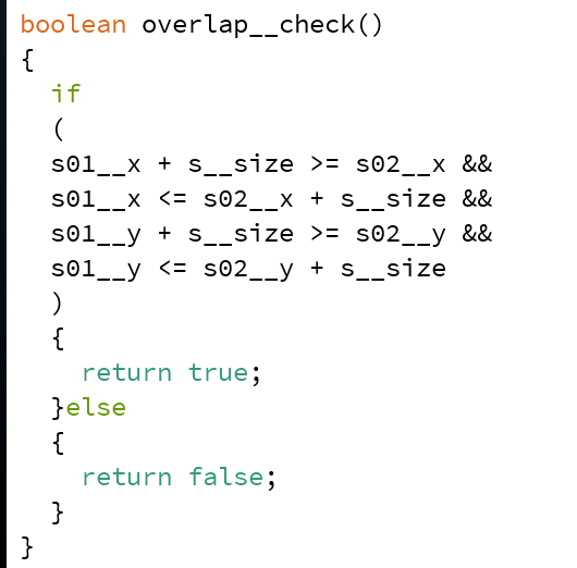 (this is also an image on purpose to get used to typing this kind of code)